
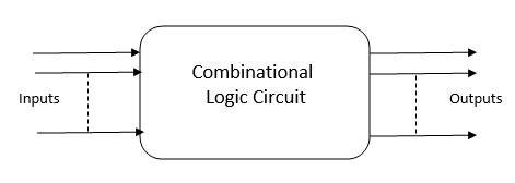
What is Combonational Logic Circuit ?
Combinational Logic Circuit হল এক ধরনের ডিজিটাল সার্কিট যাতে NAND, NOR, or NOT basic logic গেট গুলি থাকে, যেগুলো এমনভাবে সংযুক্ত থাকে যে তারা তাদের ইনপুট মানের সমন্বয়ের ভিত্তিতে নির্দিষ্ট আউটপুট তৈরি করে। এই সার্কিটগুলিতে কোনও মেমরি উপাদান নেই, যার মানে আউটপুট শুধুমাত্র বর্তমান ইনপুট মানগুলির উপর নির্ভর করে।[Combinational Logic Circuit is a type of digital circuit that consists of NAND, NOR, or NOT logic gates, which are connected in such a way that they produce specific outputs based on the combination of their input values. These circuits do not have any memory elements, which means that the output depends solely on the current input values.]
characteristics of Combinational Logic circuit
বিভিন্ন ধরনের কম্বিনেশনাল লজিক সার্কিট রয়েছে, যেমন Adder,Substractor,Multiplexer,Demultiplexer,Decoder, Encoder।
- যেকোনো মুহূর্তে, কম্বিনেশনাল সার্কিটের আউটপুট শুধুমাত্র বর্তমান ইনপুট টার্মিনালের উপর নির্ভর করে।
- কম্বিনেশনাল সার্কিটের কোনো ব্যাকআপ বা পূর্ববর্তী মেমরি নেই। সার্কিটের বর্তমান অবস্থা ইনপুটের পূর্ববর্তী অবস্থা দ্বারা প্রভাবিত হয় না।
- কম্বিনেশনাল লজিক সার্কিটে ইনপুটের x সংখ্যা এবং আউটপুটের y সংখ্যা সম্ভব।
What is Adder ?
অ্যাডার ( Adder )হল একটি ডিজিটাল সার্কিট যা দুটি বাইনারি সংখ্যা যোগ করে। বিভিন্ন ধরনের অ্যাডার রয়েছে, যেমন হাফ অ্যাডার, ফুল অ্যাডার এবং রিপল ক্যারি অ্যাডার। এখানে হাফ অ্যাডার এবং ফুল অ্যাডার সম্পর্কে আলোচনা করা হল [Adder in Digital Electronics is a digital circuit that performs the addition of two binary numbers. There are different types of adders, such as Half Adder, Full Adder, and Ripple Carry Adder. Half Adder and full adder are discussed here .]
Half Adder
Digital Electronics এ হাফ অ্যাডার (Half Adder) হল একটি ডিজিটাল সার্কিট যা দুটি একক বাইনারি সংখ্যার যোগ করতে পারে এবং একটি আউটপুট Sum এবং অপর আউটপুট Carry উৎপন্ন হয়। এটি দুটি ইনপুট টার্মিনাল এবং দুটি আউটপুট টার্মিনাল নিয়ে গঠিত। আউটপুট Sum হল ইনপুটগুলির XOR, এবং আউটপুট carry হল প্রথম এবং দ্বিতীয় ইনপুটের AND অপারেশান। [Half Adder is a digital circuit that can add two single binary digits and produce a Sum and carry output. It consists of two input terminals and two output terminals. The Sum output is the XOR of the inputs, and the Carry output is AND Opreration of first and the second input.]


Full Adder
Digital Electronics এ Full Adder হল একটি ডিজিটাল সার্কিট যা দুটি বাইনারি ডিজিট এবং একটি ক্যারি ইনপুট যোগ করতে পারে এবং একটি যোগফল এবং ক্যারি আউটপুট তৈরি করতে পারে। এটি তিনটি ইনপুট টার্মিনাল এবং দুটি আউটপুট টার্মিনাল নিয়ে গঠিত। যোগফল আউটপুট হল ইনপুট এবং ক্যারি ইনপুটের XOR এবং ক্যারি আউটপুট হল ইনপুট এবং ক্যারি ইনপুটের OR। [Full Adder is a digital circuit that can add two binary digits and a carry input and produce a sum and carry output. It consists of three input terminals and two output terminals. The sum output is the XOR of the inputs and the carry input, and the carry output is the OR of the inputs and the carry input.]


Substractor
Digital Electronics এ সাবট্র্যাক্টর( Substractor) হল একটি ডিজিটাল সার্কিট যা দুটি বাইনারি সংখ্যার বিয়োগ সম্পাদন করে। বিভিন্ন ধরণের বিয়োগকারী রয়েছে, যেমন হাফ সাবট্র্যাক্টর, ফুল সাবট্র্যাক্টর এবং বোরো বোরো সাবট্র্যাক্টর । [Subtractor is a digital circuit that performs the subtraction of two binary numbers. There are different types of subtractors, such as Half Subtractor, Full Subtractor, and Borrow Borrow Subtractor.]
Half Substractor
Digital Electronics এ হাফ সাবট্র্যাক্টর(Half Substractor) হল একটি ডিজিটাল সার্কিট যা দুটি একক বাইনারি সংখ্যা বিয়োগ করতে পারে এবং একটি আউটপুট Difference এবং অপর আউটপুট Borrow উৎপন্ন হয়। এটি দুটি ইনপুট টার্মিনাল এবং দুটি আউটপুট টার্মিনাল নিয়ে গঠিত। আউটপুট Difference হল ইনপুটগুলির XOR, এবং আউটপুট Borrow হল প্রথম ইনপুটের NOT এবং দ্বিতীয় ইনপুটের AND অপারেশান। [Half Subtractor is a digital circuit that can subtract two single binary digits and produce a difference and borrow output. It consists of two input terminals and two output terminals. The difference output is the XOR of the inputs, and the borrow output is the NOT of the first input AND the second input.]


Full Substractor ?
Digital Electronics এ ফুল সাবট্র্যাক্টর (Full Substractor) হল একটি ডিজিটাল সার্কিট যা দুটি বাইনারি ডিজিট এবং একটি Borrow ইনপুট বিয়োগ করতে পারে এবং একটি আউটপুট Difference এবং অপর আউটপুট Borrow উৎপন্ন হয়। এটি তিনটি ইনপুট টার্মিনাল এবং দুটি আউটপুট টার্মিনাল নিয়ে গঠিত।[Full Subtractor is a digital circuit that can subtract two binary digits and a borrow input and produce a difference and borrow output. It consists of three input terminals and two output terminals. ]


Multiplexer
মাল্টিপ্লেক্সার হল একটি ডিজিটাল সার্কিট যা অনেক ইনপুট সিগন্যালের মধ্যে একটি নির্বাচন করতে পারে এবং এটিকে আউটপুটে প্রেরণ করতে পারে। এটি একাধিক ইনপুট টার্মিনাল, একটি সিলেক্ট ইনপুট টার্মিনাল এবং একটি আউটপুট টার্মিনাল নিয়ে গঠিত। সিলেক্ট ইনপুট নির্ধারণ করে কোন ইনপুট সিগন্যালটি আউটপুটে যাবে।[Multiplexer is a digital circuit that can select one of many input signals and pass it through to the output. It consists of multiple input terminals, a select input terminal, and an output terminal. The select input determines which input signal is passed through to the output.]
Example: 4×1 MUX
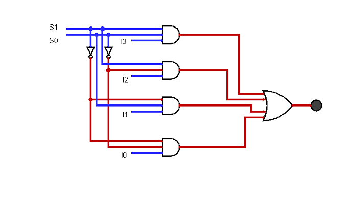
4×1 মাল্টিপ্লেক্সারে, মোট চারটি ইনপুট রয়েছে, যেমন, I0, I1, I2,, এবং I3, 2টি নির্বাচন লাইন(Selection line), যেমন, S0 এবং S1 এবং একক আউটপুট, অর্থাৎ, Y. এর সমন্বয়ের ভিত্তিতে যে ইনপুটগুলি নির্বাচন লাইন S0 এবং S1 এ উপস্থিত থাকে, এই 4টি ইনপুটের মধ্যে একটি আউটপুটের সাথে সংযুক্ত থাকে। 4×1 মাল্টিপ্লেক্সারের ব্লক ডায়াগ্রাম এবং সত্য সারণী নিচে দেওয়া হল। [In the 4×1 multiplexer, there is a total of four inputs, i.e., I0, I1, I2, and I3, 2 selection lines, i.e., S0 and S1 and single output, i.e., Y. On the basis of the combination of inputs that are present at the selection lines S0 and S1 , one of these 4 inputs are connected to the output. The block diagram and the truth table of the 4×1 multiplexer are given below.]


উপরের সত্য সারণী অনুযায়ী আউটপুট এর লজিক এক্সপ্রেশন হল [According to above truth table logic exoression of output y is]- Y=S1′ S0′ I0+S1′ S0 I1+S1 S0′ I2+S1 S0 I3
Demultiplexer
Demultiplexer হল একটি ডিজিটাল সার্কিট যা একটি ইনপুট সিগন্যাল নিতে পারে এবং একাধিক আউটপুট সিগন্যালে বিতরণ করতে পারে। এটি একটি ইনপুট টার্মিনাল, একাধিক নির্বাচিত(select) ইনপুট টার্মিনাল এবং একাধিক আউটপুট টার্মিনাল নিয়ে গঠিত। নির্বাচিত(select)ইনপুটগুলি নির্ধারণ করে যে কোন আউটপুট টার্মিনালে ইনপুট সংকেতটি পাস করা হয়েছে।[Demultiplexer is a digital circuit that can take one input signal and distribute it to multiple output signals. It consists of one input terminal, multiple select input terminals, and multiple output terminals. The select inputs determine which output terminal the input signal is passed through to.]
Exmaple: 1×4 DEMUX:
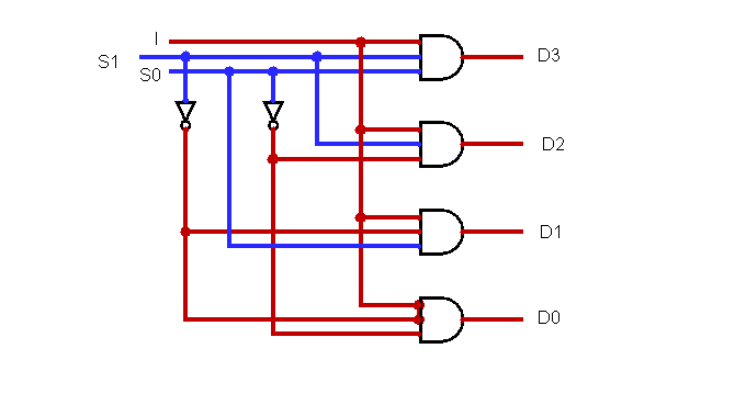
1×4 ডি-মাল্টিপ্লেক্সারে, মোট চারটি আউটপুট রয়েছে, যেমন, D0, D1, D2, এবং D3, 2টি নির্বাচন লাইন(selection line), যেমন, S0 এবং S1 এবং একটি ইনপুট, অর্থাৎ, I. এর সমন্বয়ের ভিত্তিতে যে ইনপুটগুলি নির্বাচন লাইন S0 এবং S1 এ উপস্থিত থাকে, ইনপুটটি আউটপুটের একটির সাথে সংযুক্ত থাকে। 1×4 মাল্টিপ্লেক্সারের ব্লক ডায়াগ্রাম এবং সত্য সারণী নীচে দেওয়া হল।
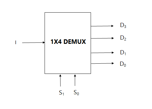
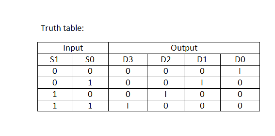
উপরের সত্য সারণী অনুযায়ী আউটপুট এর লজিক এক্সপ্রেশন হল [According to above truth table logic exoression of output is]-
D0=S0‘S1‘I
D1=S0 S1‘ I
D2=S0‘ S1 I
D3=S0 S1 I
Decoder & Decoding
ডিকোডার হল একটি ডিজিটাল সার্কিট যা একটি বাইনারি ইনপুট নিতে পারে এবং ইনপুট মানের উপর ভিত্তি করে অনেক আউটপুট সংকেতের মধ্যে একটি সংকেত কে সক্রিয় করতে পারে। এটি একাধিক ইনপুট টার্মিনাল এবং একাধিক আউটপুট টার্মিনাল নিয়ে গঠিত। ইনপুট মানের সাথে সম্পর্কিত আউটপুট টার্মিনাল সক্রিয় হয়, অন্য সমস্ত আউটপুট টার্মিনাল নিষ্ক্রিয় থাকে। [Decoder is a digital circuit that can take a binary input and activate one of many output signals based on the input value. It consists of multiple input terminals and multiple output terminals. The output terminal that corresponds to the input value is activated, while all other output terminals remain inactive.]
Example: 2×4 decoder
2×4 লাইনের ডিকোডারে, মোট তিনটি ইনপুট রয়েছে, যেমন, I0, এবং I1 এবং E এবং চারটি আউটপুট, যেমন, D0, D1, D2 এবং D3। ইনপুটগুলির প্রতিটি সংমিশ্রণের জন্য, যখন সক্ষম ‘E’ 1 তে সেট করা হয়, তখন এই চারটি আউটপুটের মধ্যে একটি হবে 1। ব্লক ডায়াগ্রাম এবং 2 থেকে 4 লাইনের ডিকোডারের সত্য সারণী নীচে দেওয়া হয়েছে।
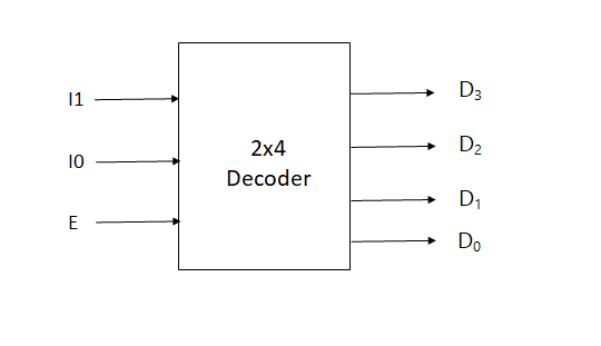

উপরের সত্য সারণী অনুযায়ী আউটপুট এর লজিক এক্সপ্রেশন হল [According to above truth table logic exoression of output is]-
D3=E.I1.I0
D2=E.I1.I0‘
D1=E.I1‘.I0
D0=E.I1‘.I0‘

Encoder & Encoding
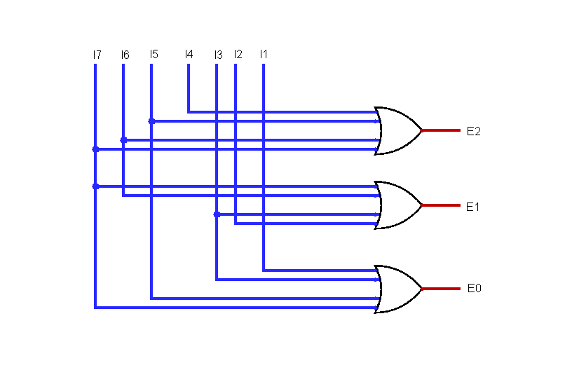
এনকোডার হল একটি ডিজিটাল সার্কিট যা একাধিক ইনপুট সিগন্যাল নিতে পারে এবং সেগুলিকে একক বাইনারি আউটপুট সিগন্যালে রূপান্তর করতে পারে। এটি একাধিক ইনপুট টার্মিনাল এবং একটি একক আউটপুট টার্মিনাল নিয়ে গঠিত। ইনপুট সিগন্যালের বাইনারি মান আউটপুট সিগন্যালের জন্য একটি বাইনারি মানে রূপান্তরিত হয়। [Encoder is a digital circuit that can take multiple input signals and convert them into a single binary output signal. It consists of multiple input terminals and a single output terminal. The binary value of the input signals is converted into a binary value for the output signal.]
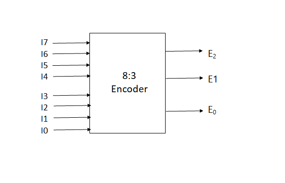
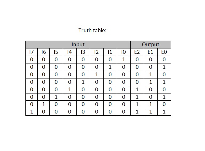
উপরের সত্য সারণী অনুযায়ী আউটপুট এর লজিক এক্সপ্রেশন হল [According to above truth table logic exoression of output is]-
E2=I4+I5+I6+I7
E1=I2+i3+I6+I7
E0=I7+I5+I3+I1